VRRP Configuration between a Cisco IOS XE and Junos Router
Let's take a look at the configuration required for a multi-vendor VRRP deployment. For this post, we'll be using a Cisco CSR 1000v router and a virtual SRX router by Juniper; the configuration may be adjusted to work on other Cisco and Juniper device families.
What is VRRP?
It is essentially a protocol for redundancy.
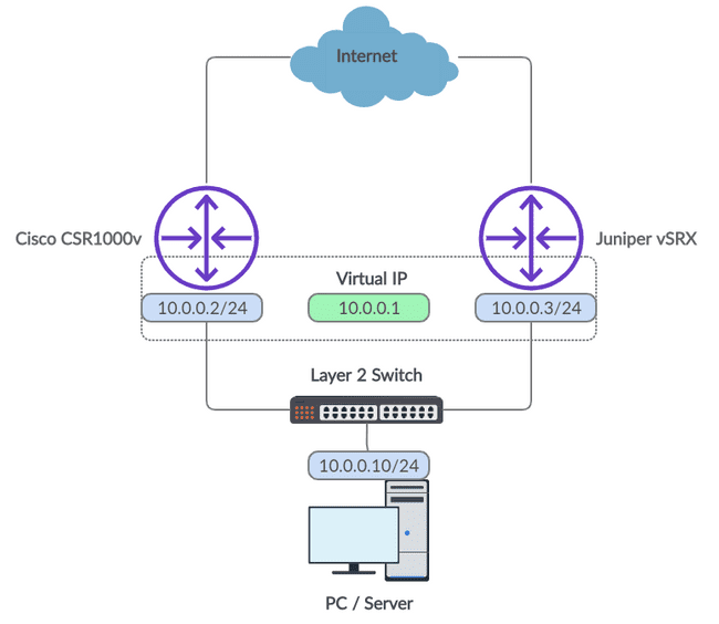
Let's use a simple use case to explain it. Imagine you're browsing the Internet on a PC and your default gateway crashes. Naturally, you'll be interrupted as you lose your Internet connection. With VRRP configured, however, this scenario can be avoided. Take a look at the diagram below of a basic VRRP set up on a customer edge (keep in mind that VRRP is great within a provider core too).
Figure 1: VRRP Network Diagram
VRRP, the Virtual Router Redundancy Protocol, allows an IP address to be shared between two different network devices; this address is referred to as the Virtual IP. In our network diagram, we have a Virtual IP of 10.0.0.1. This would be used as the default gateway of our PC or another client we have connected downstream.
Our two routers, the Cisco and Juniper devices, are assigned physical interfaces on the same network as the client and are all tied together with a layer 2 switch. This provides the two routers with connectivity to each other so they may undergo VRRP elections where master and backup roles are assigned.
The Virtual IP will always exist on the master router. In the event of a failure on the master router, the backup router will automatically begin the election process once again. As the backup device is the only device left within the VRRP group it will assign itself the master role and take control of the Virtual IP. By consequence, traffic from the client will now traverse via the new master.
Let's build our VRRP lab
With that said, let's jump into the actual configuration required for our example diagram.
Beginning with the Cisco device, enter configuration mode.
conf tHow to configure a VRRP interface on Cisco
Next, configure the physical interface and create the VRRP group.
interface GigabitEthernet1
 ip address 10.0.0.2 255.255.255.0
 vrrp 1 ip 10.0.0.1
 vrrp 1 priority 90
 no shut
 end
The "1" which comes after the "vrrp" keyword refers to the VRRP group number. This enables multiple VRRP groups to be configured using unique identifiers if required. The 10.0.0.1 value configured is simply the Virtual IP for our group. And finally, the priority value configured will be used in the election process to decide which router will take the master role. The router with the highest priority value is elected as the master.
That is all we need on the Cisco device! We may now jump into the configuration required for the Junos router.
How to configure a VRRP interface on Juniper
Similarly, enter configuration mode.
configureWe can now add the configuration for our physical interface and VRRP group.
set interfaces ge-0/0/0 unit 0 family inet address 10.0.0.3/24 vrrp-group 1 virtual-address 10.0.0.1
set interfaces ge-0/0/0 unit 0 family inet address 10.0.0.3/24 vrrp-group 1 priority 50
set interfaces ge-0/0/0 unit 0 family inet address 10.0.0.3/24 vrrp-group 1 accept-data
Syntax aside, the configuration applied here is very similar to the Cisco router. You'll notice that the priority value we applied is less than the value we added to the Cisco router so our Junos device will assume the backup role under normal operation. Also, we included the "accept-data" config. Without this inclusion, the Junos device would only accept ARP traffic destined to the Virtual IP.
Finally, to perform ICMP testing and enable VRRP you will need to prevent this traffic from being blocked.
set security zones security-zone trust host-inbound-traffic system-services ping
set security zones security-zone trust host-inbound-traffic protocol vrrp
set security zones security-zone trust interfaces ge-0/0/0
Commit the configuration.
commit and-quitHow to verify VRRP is running correctly
VRRP should now be running correctly. We can check the VRRP status to ensure this is the case. For the Junos device, ensure the VR state has the value "backup".
root@vSRX> show vrrp
Interface     State       Group   VR state VR Mode   Timer    Type   Address
ge-0/0/0.0    up              1   backup   Active      D  3.068 lcl    10.0.0.3
                                                                vip    10.0.0.1
                                                                mas    10.0.0.2
For the Cisco router, ensure the VR state has the value "Master".
CSR1000v# show vrrp
GigabitEthernet1 - Group 1
  State is Master
  Virtual IP address is 10.0.0.1
  Virtual MAC address is 0000.5e00.0101
  Advertisement interval is 1.000 sec
  Preemption enabled
  Priority is 90
  Master Router is 10.0.0.2 (local), priority is 90
  Master Advertisement interval is 1.000 sec
  Master Down interval is 3.648 sec
Let's simulate a link failure
We may now perform a practical test. Setup a continuous ping test from the client device to the Virtual IP.
Next, shut down the interface on the Cisco router.
CSR1000v#conf t
Enter configuration commands, one per line.  End with CNTL/Z.
CSR1000v(config)#interface GigabitEthernet1
CSR1000v(config-if)#shut
CSR1000v(config-if)#
*Jul 20 00:41:45.721: %VRRP-6-STATECHANGE: Gi1 Grp 1 state Master -> Init
*Jul 20 00:41:47.723: %LINK-5-CHANGED: Interface GigabitEthernet1, changed state to administratively down
*Jul 20 00:41:48.723: %LINEPROTO-5-UPDOWN: Line protocol on Interface GigabitEthernet1, changed state to down
CSR1000v(config-if)#end
You should now observe an output similar to that of the above. The backup device will be elected as the new master. The continuous ping from the client should have only momentarily been interrupted.
You can verify that the failover occurred from the Junos device too. The VR state should now have the value "master".
root@vSRX> show vrrp
Interface     State       Group   VR state VR Mode   Timer    Type   Address
ge-0/0/0.0    up              1   master   Active      A  0.435 lcl    10.0.0.3
                                                                vip    10.0.0.1
Hopefully, these examples helped your understanding of VRRP in a multi-vendor environment. If you have any questions, feel free to leave a comment beneath the post and we'll do our best to help.
Ultra Config Generator
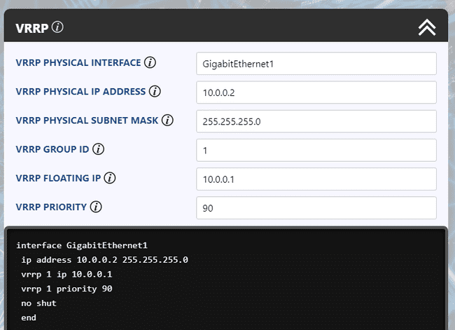
You can download two templates of the configuration discussed below and import them into your Ultra Config Generator instance. A screenshot of the Cisco template in action is shown for illustration.
Download:
vrrp-cisco-2019-07-20.json
vrrp-juniper-2019-07-20.json
Figure 2: UCG VRRP Template for Cisco
If you haven't heard of Ultra Config Generator, I would highly recommend you check it out. We designed the product to allow network engineers to generate and automate network configuration in a highly flexible, efficient and elegant manner. Our users love the application and I hope that you will too.
Take care until next time!
Ultra Config
JOIN THE DISCUSSION
Subscribe to the Blog
Subscribe now and never miss a new post!
Success! You'll now receive emails when new blogs are posted.

